Chapter 5 - Fuselage Sides
Chapter 4 was about making a bunch of bulkheads which are all internal to the fuselage structure. Chapter 5 involves making external parts - the fuselage sides.
In this chapter, only the interior faces of the fuselage sides will be glassed. The exterior faces will be glassed in chapter 7, when the fuselage is assembled.
Current Status: Finished! ✅ 2022-12-13
FJ* Jigs
Status: ✅ 2022-10-30
| Template | Status |
|---|---|
| FJA | ✅ |
| FJB | ✅ |
| FJC | ✅ |
| FJD | ✅ |
| FJE | ✅ |
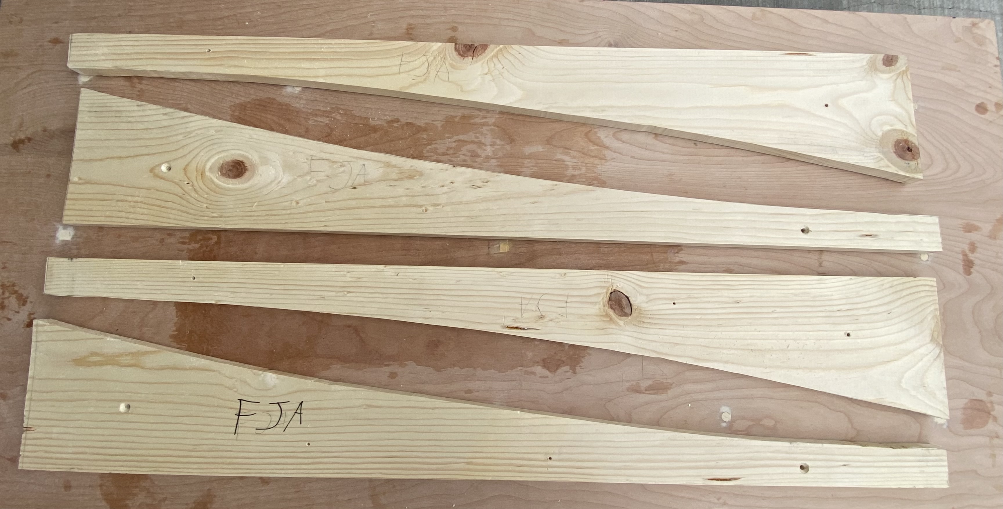
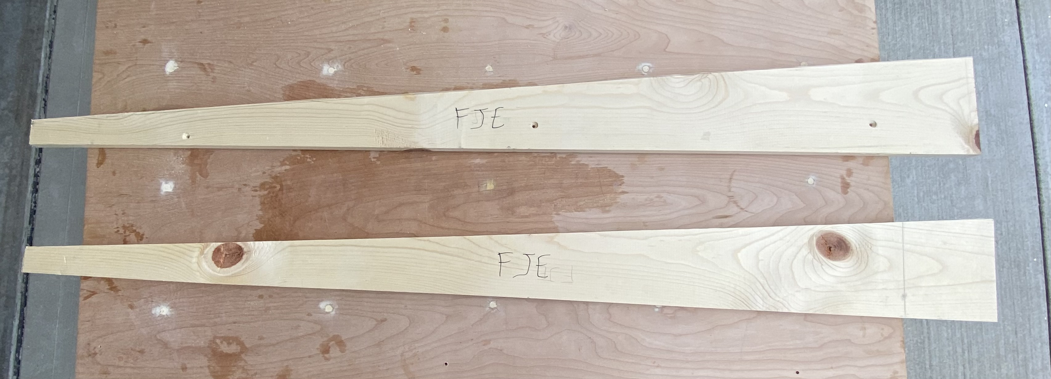
The FJ* jigs are used for shaping the longerons and providing a shape for the foam that will be epoxied. For the most part, these are cut from 1 by 8 (nominal) pine board. For the FJA jig, with the curve over the length of it, I chose to 3d print a template for it, which I’ll use to copy onto pine board using a trim bit in my router. I also 3d printed the FJD jig, but as I was cutting FJB, I realized that it wasn’t that much more effort to also create a pine version of FJD as well. Which works better because it’s easier to drill in nails to wood.
Fuselage Side Forms
Status: ✅ 2022-11-08
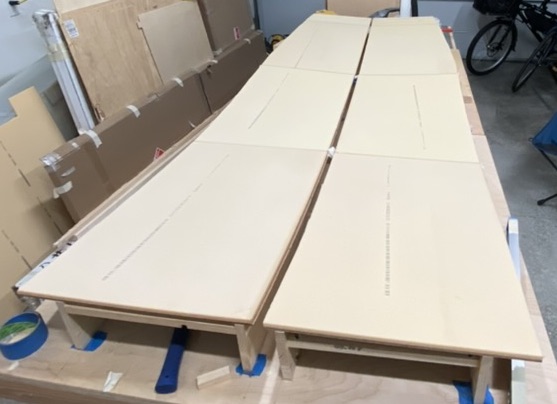
The fuselage sides need a form to rest on, otherwise they’ll sag and not be the correct side. Per plans, I got a large sheet of masonite, and used it to create forms for the 2 fuselage sides. I did this by ripping it into 2x 21 inch wide by 8 foot long sheets, keeping the scrap. The scrap was used to extend the width of these sheets to the necessary 102.5 inches. Note: I accidentally cut my strips of scrap too short, by about an inch or so. I don’t think it’ll make that much of a difference (and if it will, I’ll add on that extra inch or so of material).
Once the forms were at their full length, I aligned them on top of each other and drew out the points for the shape. Then connected the points with straight lines, then tried my best to cut it using a jigsaw. This produced two forms of the exact same shape, which I’ll use to help shape the fuselage side foam.
Upper Longerons
Status: ✅ 2022-11-08
Tips:
- Place the forward doubler about 0.5“ back from where the plans indicate. This prevents a canard placement issue that many people report.
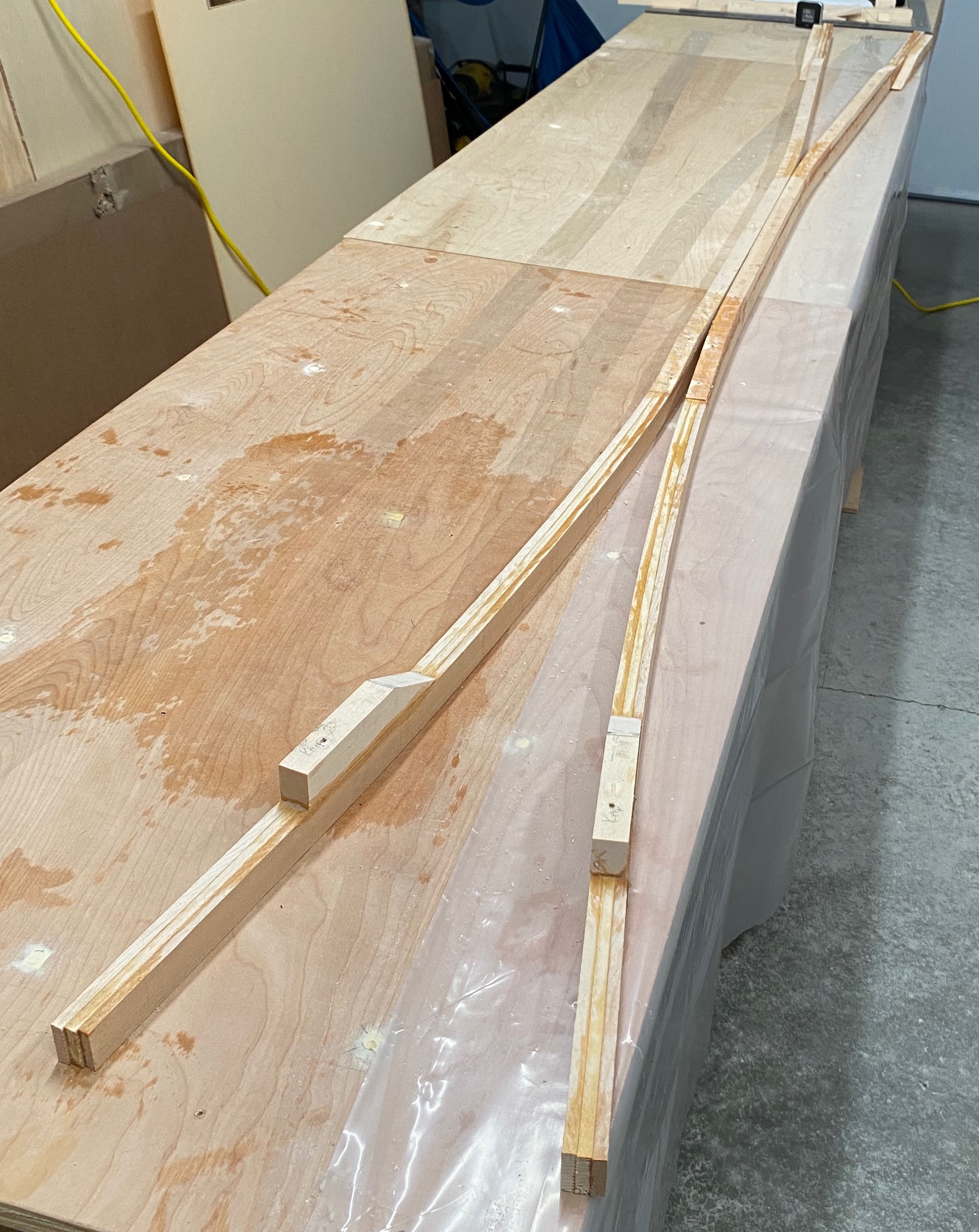
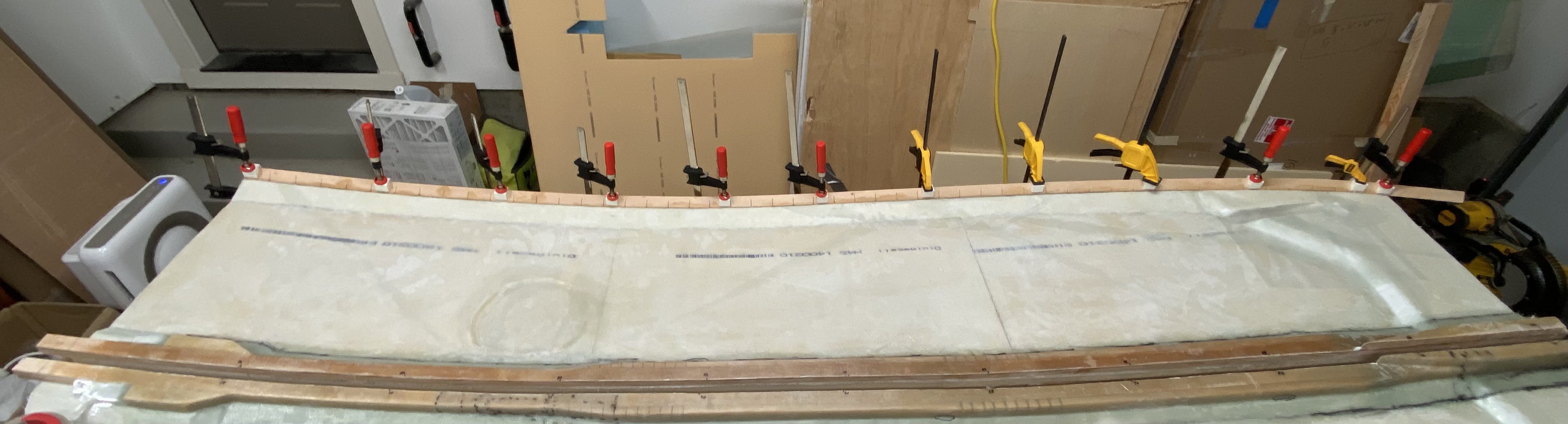
The upper longerons (one for each side) are made of 3 long strips of 1“ by 0.25“ by 105“ sitka spruce. Along with a stiffener and 2 doublers, also made of spruce. Because these will go on top of the foam for the fuselage sides, they need to have a slightly tighter curve than the fuselage sides. This is done by laying FJA, FJB, and FJC on their sides, with the ends of FJA and FJC being 0.5“ apart, but angled so that they are adjacent by the time they meet FJB. Once you have the jigs set up, you’re supposed to join the 105“ spruce by painting the interiors, then use clamps & nails to hold the wood to the jigs. I was able to get away using just clamps.
Once the epoxy cured, I added the doublers and stiffeners. Per plans, I pre-drilled holes for nails on the forward doublers and the stiffeners. Then, once the wet flox was mixed up, I painted it on to the forward and aft doublers. For the center stiffeners, I found it easier to paint the flox onto the spruce strips, not the stiffeners. I also added regular flox into the saw holes, to try to counteract the fact that I made way more saw holes than I needed to. Once everything was epoxied and in place, I re-clamped everything, then added weights.
You’re supposed to let this whole thing cure for at least a 24 hours. I let it cure for more than that. This is because when I initially installed the doublers, I mistakenly placed the aft doublers in the wrong orientation (I had it aligned such that the taper was aligned with the curve of the longeron. You’re supposed to have that taper be facing up). I didn’t realize this error until I was preparing to go to bed, ~4 hours later. I got up and re-installed the aft doublers in the correct position (and checked with the plans multiple times while I was doing so - didn’t want to make an error because I was tired). Everything worked out, but it did mean that it would be way more convenient to just let it cure an additional night (and work on something else for once).
Fuselage Sides
Status: ✅ 2022-11-14
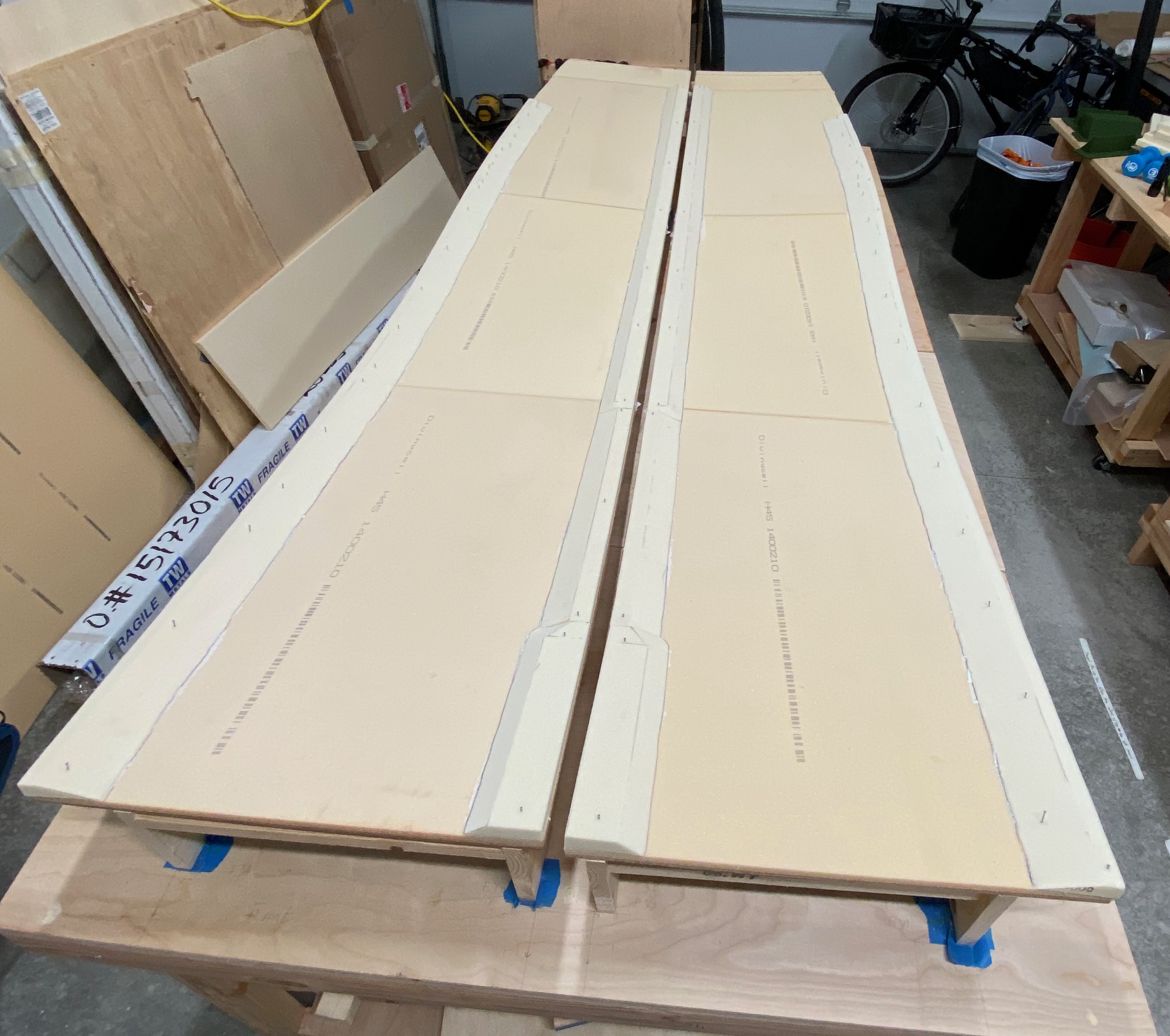
The plans state to hot glue the fuselage jigs to your workbench. Which is what I started to do, except I ran into issues both with my workbench not being sufficiently level (one of the main downsides of wanting to create a large workbench from several smaller workbenches - leveling them is nearly impossible), and with the jigs themselves having twist and otherwise not being perfectly straight. So instead, I made a series of spacers that I glued & screwed into place to keep the jigs the correct distance apart. This forms kind of the skeleton of a box, and is why I’m calling it a jig box.
Once you’ve done that, you’re supposed to place down the fuselage forms, and nail them in place. Per Wayne Hicks, you should only nail to the inside corner to ensure that the forms have entirely convex curves.
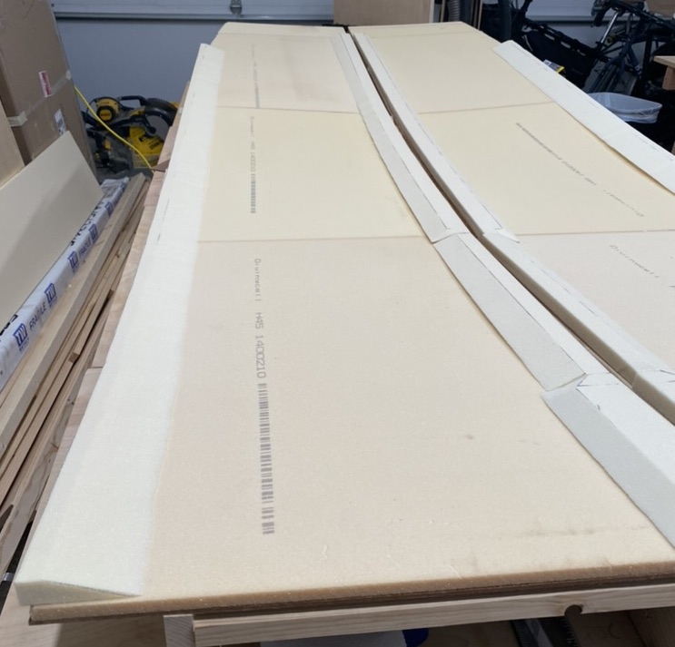
Ideally, prior to this point, you should have cut & joined your foam. Which I did not do. Instead, I placed the foam on the forms, then I used a sharpie to trace the outside curve (the non-straight edge). After, I cut the foam along traced lines, then sanded it smooth. Which worked, but was annoying. Afterwards, I then joined the foam panels together in-place on the forms. Which, again. I should have done that on a flat surface, but I didn’t really have one available. It worked out, but just took longer and more effort than it should have been.
Once you have the foam put together, you’re supposed to secure it directly to the forms using 5-minute epoxy. People have had issue with the foam tearing upon removal. I thought I’d be clever by applying painters tape to both the form and the foam, then applying 5-minute epoxy between the painters tape. Except the painters tape did not actually adhere to the foam. The next day, I came back and used masking tape, which worked immensely better.
Fuselage Side Spacers & Control Stick Depressions
Status: ✅ 2022-11-20
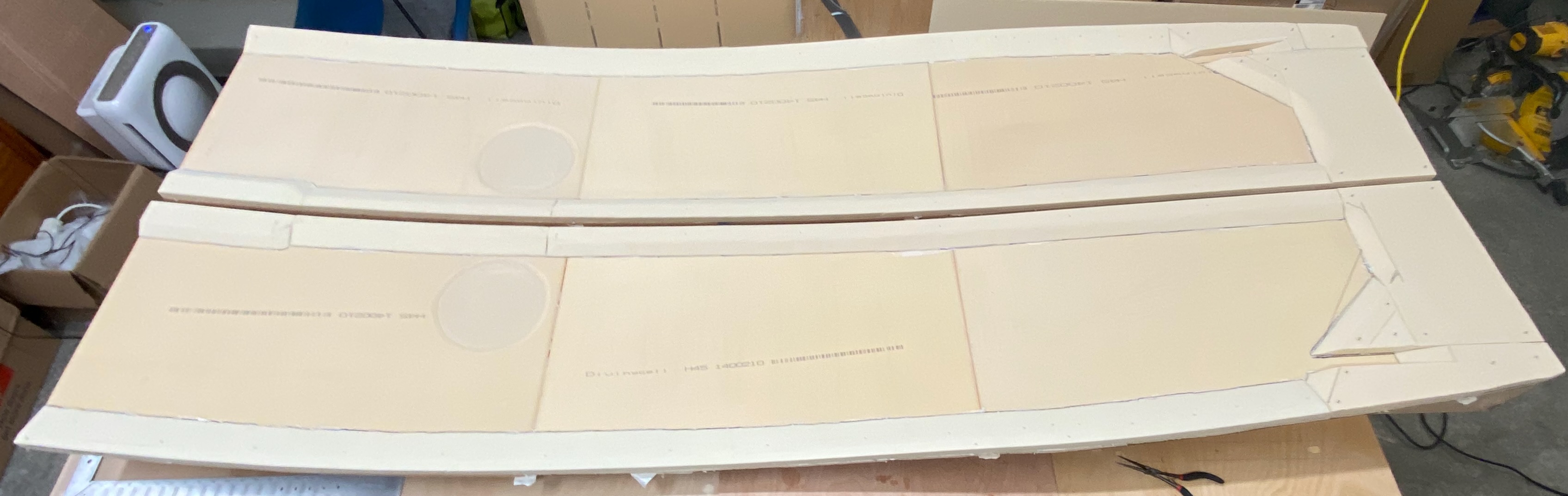
Once I had the foam secured, I started cutting the side spacers. These spacers are 3/4“ low-density last-a-foam that are supposed to to be micro’d to the top, bottom and aft edges of each side panel. Unlike the high-density last-a-foam used in F-22, F-28 and the instrument panel from chapter 4, this low-density stuff cuts very easily with a utility knife.
I cut out the spacers for the top and bottom, then 3d printed jigs so I could easily cut them on my bandsaw at the angles described in the plans. Once these had been cut, I installed them to the fuselage sides with wet micro (albeit, it was on the dry side of wet micro). As per plans, I used finishing nails to help hold them down + maintain shape.
While the top and bottom spacers cured, I went about figuring out the dimensions for the aft spacers. This was mostly done by eyeballing it, along with what little precise dimensions are given by the plans. It’s good enough. Again, I installed these with wet micro. While they cured, I used a router to add the depressions for the control sticks. For a gas-powered cozy, this is also where you’d create the depressions for the fuel sight gauges. I’m building an electric cozy. I don’t need fuel sight gauges. While I could take off a few grams by creating these depressions, it’s not going to make a difference one way or another.
Fuselage Side Interior Layup
Status: ✅ 2022-11-26
The Interior Fuselage Side Layup is the first large layup you do. This is glassing the interior faces of the entire fuselage sides. It’s a source of a lot of trouble for many people. I came away relatively unscathed.
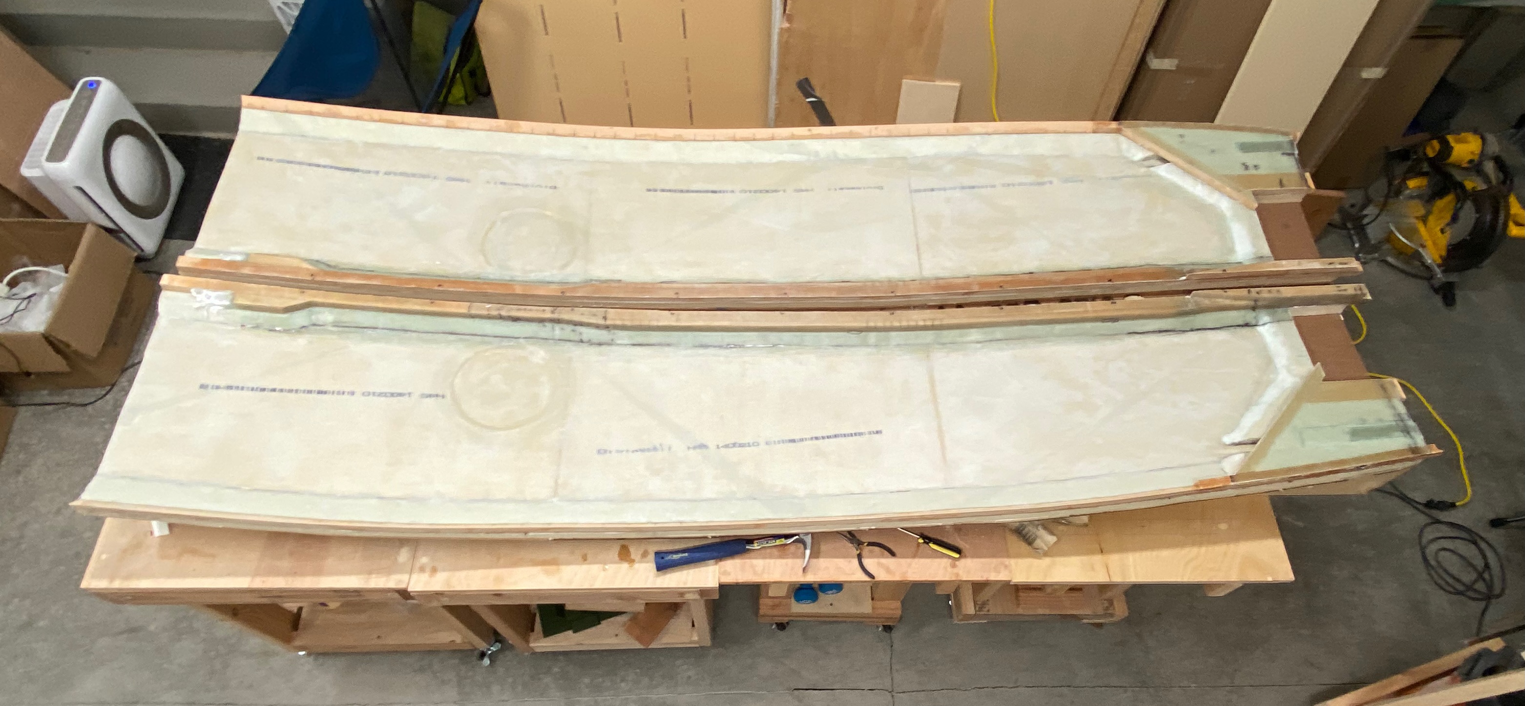
A few days later after installing the spacers, my wife was available to help glass the fuselage side interiors. You could probably do this layup without any help, but her help made this immensely easier and much faster. Even with her help, this took close to 6 hours to complete. The first task was to coat all of the foam with micro, which took about 2 hours on its own. Then, with my wife’s help, we laid down the UNI fiberglass on the foam. You’re supposed to add 2 layers of UNI, at 30° fiber orientation from horizontal, with one layer oriented mostly forward to aft, and the other oriented in a forward-facing direction. Once the UNI was laid down, we massaged it into place. It’s really important to get the fibers to conform to all of the curves and corners, which was a little bit of a pain, but we managed to do it with minimal wrinkles. Once that was wetted out, we laid down the second layer of UNI and wet it out. Again, we had some minor difficulties with handling the complex curves, but we got it. Once this layer was fully wetted out, we grabbed a flashlight and double checked the layup for any potential issues. We came across a few, but took care of them. Then, I grabbed the upper longerons, and my wife painted the mating faces with wet flox while I held them. I placed them onto the fuselage sides then clamped them down. Then, we put down peel ply everywhere, and let it sit.
After letting it cure for an hour, I pulled off the peel ply to discover the results of my work. I was very pleased with the result. Yes, there were bubbles, but they were all repairable. Most were repairable with a simple injection of epoxy, which was incredibly satisfying to do. However, a few required me to sand off the fiberglass and re-apply it. In some of these cases, I ended up sanding off too much of the foam. For those cases, I applied dry micro as a filler to get to the desired shape. In the end, I’m very happy with the results.
Glassing the Upper Longerons
Status: Awaiting Cure
Once the fuselage side layup was finished and repaired, I moved on to glassing the upper longerons. Frankly, this was my least favorite layup I’ve done so far. It’s a large layup, but the overall section widths were very small, as well as some vertical sections. Which meant that I couldn’t really use a squeegee to spread epoxy. So I had to stipple pretty much the entire layup. I squeegeed as much as I could, to both improve the speed as well as to remove air bubbles and voids. But still, this was not a fun layup.
Because the upper longeron forward of F-28 will be getting cut off in a future chapter, I did not bother glassing forward of the forward doubler.
This layup turned out horribly. Bubbles galore and even some delaminations. Most of the issues were along the wood longerons, and only really the first 2 or 3 layers deep. Still frustrating. After spending a few days dreading this, I sanded off most of the fiberglass. This took 2 days. The day after that, I re-glassed the upper longerons. This second layup turned out significantly better - I only identified 3 issues, and then 2 more that actually looked like non-issues when I re-examined while repairing the other 3. I decided to let the epoxy finish curing for another day before repairing.
Two days after that, I performed the second repair of the upper longeron.
The Lower Longerons
Measuring & Marking the Lower Longerons
The plans are slightly unclear on how you’re supposed to make sure the lower longerons are correctly installed. The important thing is that the lower longerons need to be installed such that each side exactly matches - each lower longeron needs to be exactly the same distance from the corresponding upper longeron. They should be close to the numbers specified in figure 5, but since it’s impossible to actually get that correct (considering you’re now measuring on a curved surface, when figure 5 is for a flat surface), the distances just need to be close to what figure 5 specifies. I measured the distance with a carpenter’s square, using wood spacers to avoid any error from measuring a vertical distance. I recorded the distances at 10 inch intervals, and then computed their differences. After, I marked the insets on the relevant sides, where relevant. Then I prepared for glassing. Here are the values I measured, along with what figure 5 specifies:
| Distance from forward Edge (inches) | Port Side Distance (inches) | Starboard Side Distance (inches) | Difference (inches) | Value Specified in Fig. 5 (inches) |
|---|---|---|---|---|
| 0 | 20 2/16 | 20 2/16 | 0 | 20.1 |
| 10 | 20 11/16 | 20 10/16 | 1/16 | 20.6 |
| 20 | 20 15/16 | 20 14/16 | 1/16 | 20.9 |
| 30 | 20 15/16 | 21 1/16 | -2/16 | 20.9 |
| 40 | 20 13/16 | 20 13/16 | 0 | 20.9 |
| 50 | 20 14/16 | 20 14/16 | 0 | 20.85 |
| 60 | 20 14/16 | 20 12/16 | 2/16 | 20.8 |
| 70 | 20 10/16 | 20 8/16 | 2/16 | 20.5 |
| 80 | 19 12/16 | 19 13/16 | -1/16 | 20.0 |
| 90 | 18 13/16 | 18 14/16 | -1/16 | 19.0 |
| 100 | 17 9/16 | 17 14/16 | -5/16 | 17.7 |
| Aft Edge | 17 2/16 | 17 1/16 | 1/16 | 17.25 |
So, they’re fairly close to each other, and relatively close to the values specified in figure 5.
Installing the lower longerons
The plans state to add saw cuts on the inside every 4 inches, then every 2 inches where the curvature is sharper. A bunch of other builders have reported better success with doubling that - making cuts every 2 inches and every inch in sharper curves. Which I also did. Additionally, I made these cuts using a thin blade on my oscillating tool, so I feel that the more-frequent cuts will better help with this curve.
To aid with clamping the lower longerons to the fuselage sides, most builders make wood blocks with a convex inner 45° corner to match the triangular lower longeron piece. I decided that the best route for me was to instead model these jigs in CAD and 3d print them. I modeled 1 up, printed a test print to verify it works. After checking that I had the dimensions correct, I printed a bunch more of them.
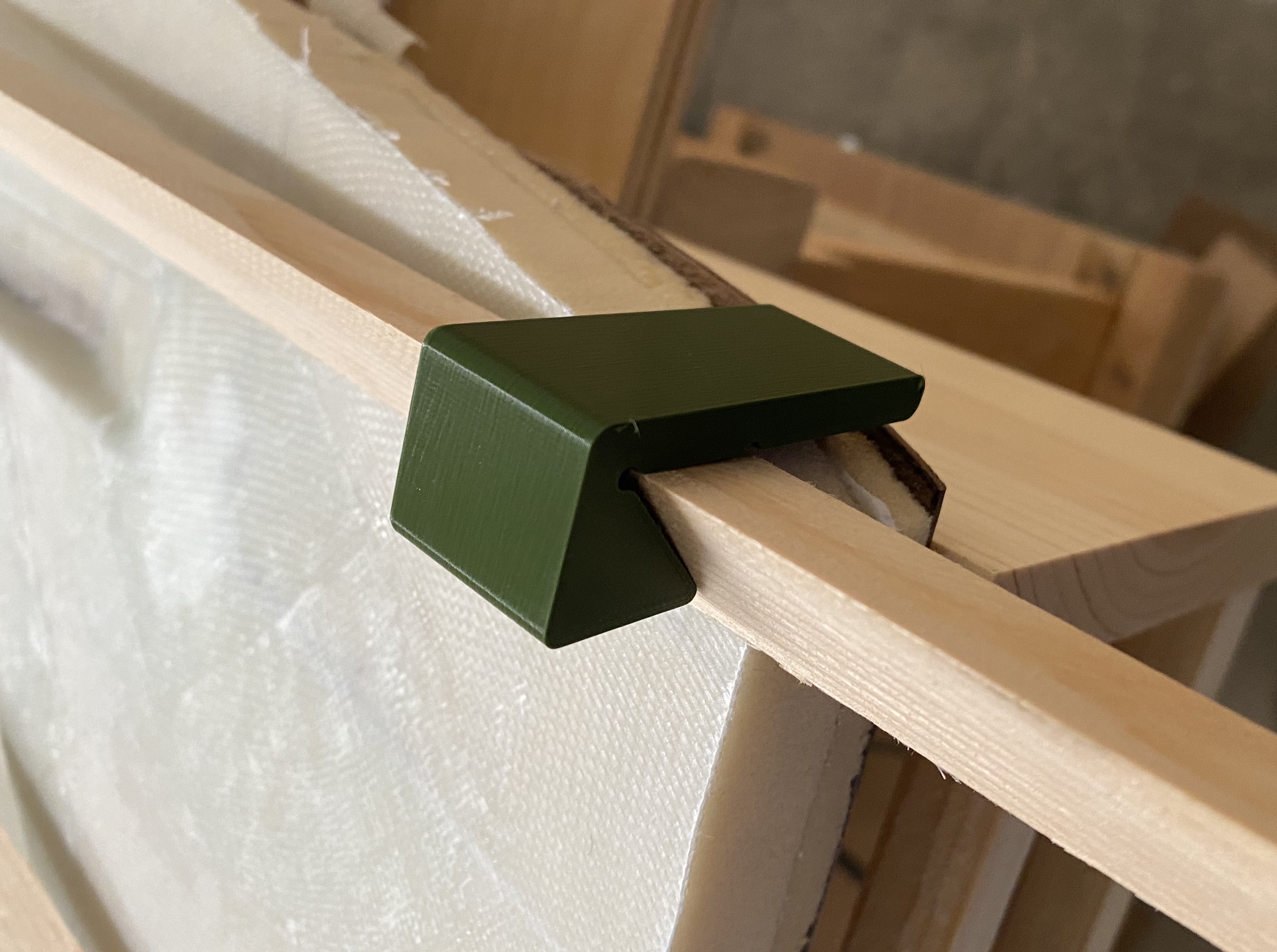
In actual usage, these ended up being a bit too long, and I ended up cutting off some of the tabs with an oscillating tool. Afterwards I redesigned the jig to remove that extra tab. For those interested, there’s an STL with this updated design.

With these clamp jigs, I installed the lower longerons. I didn’t want to bother with using nails to hold the wood in place, so instead I used clamps with the clamp jigs. I didn’t have enough clamps to install both triangular lower longerons at once, so I installed them on two separate days.
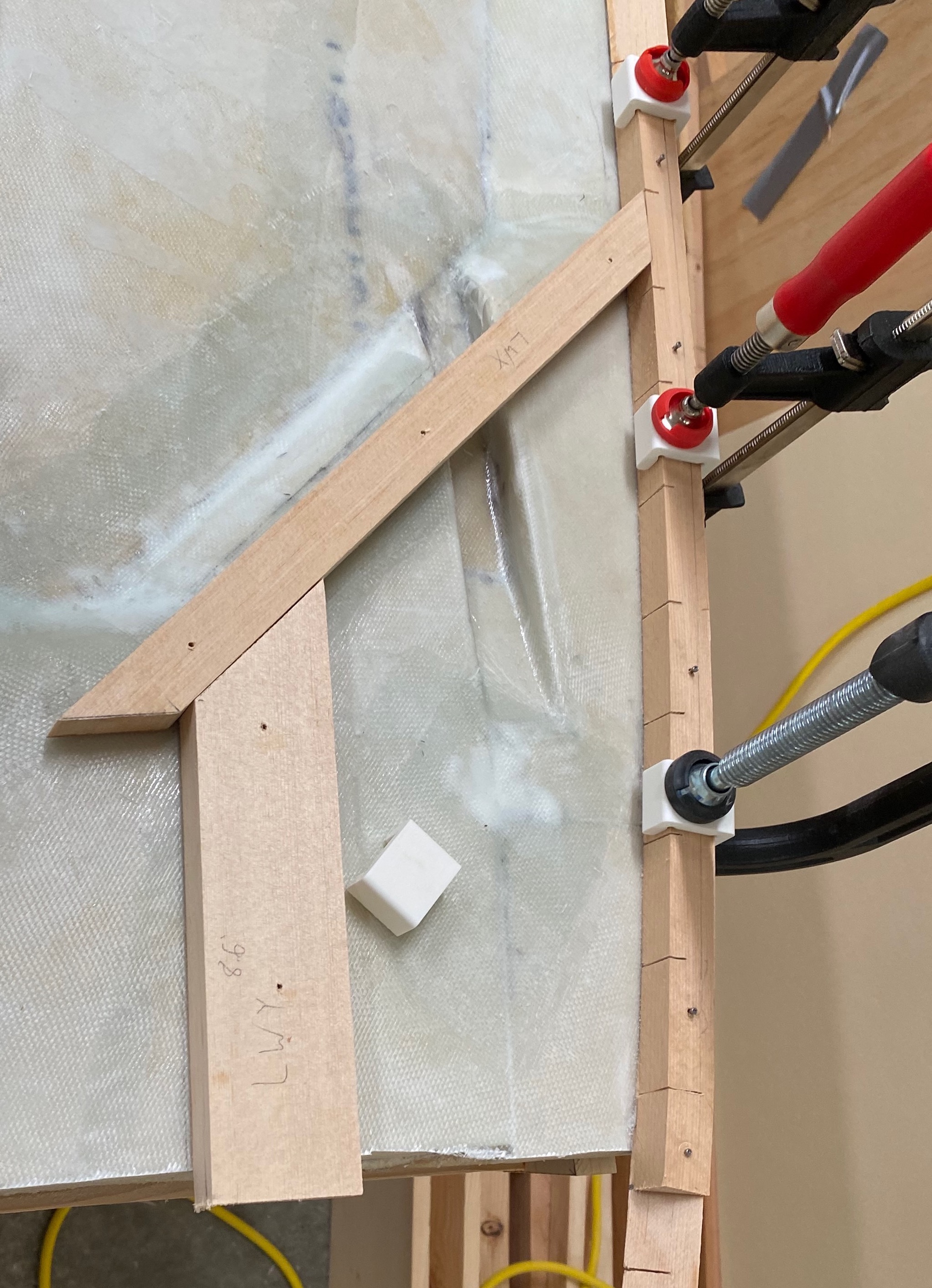
After both port and starboard lower longerons were installed, I added the longeron doublers - a 20“ long piece of triangular spruce which joins both lower longerons at the aft end along the hypotenuse side. I also measured and installed the LWX and LWY stringers. These are used to provide additional stability and better anchor the landing gear to the rest of the airplane.
Completing the Fuselage Sides
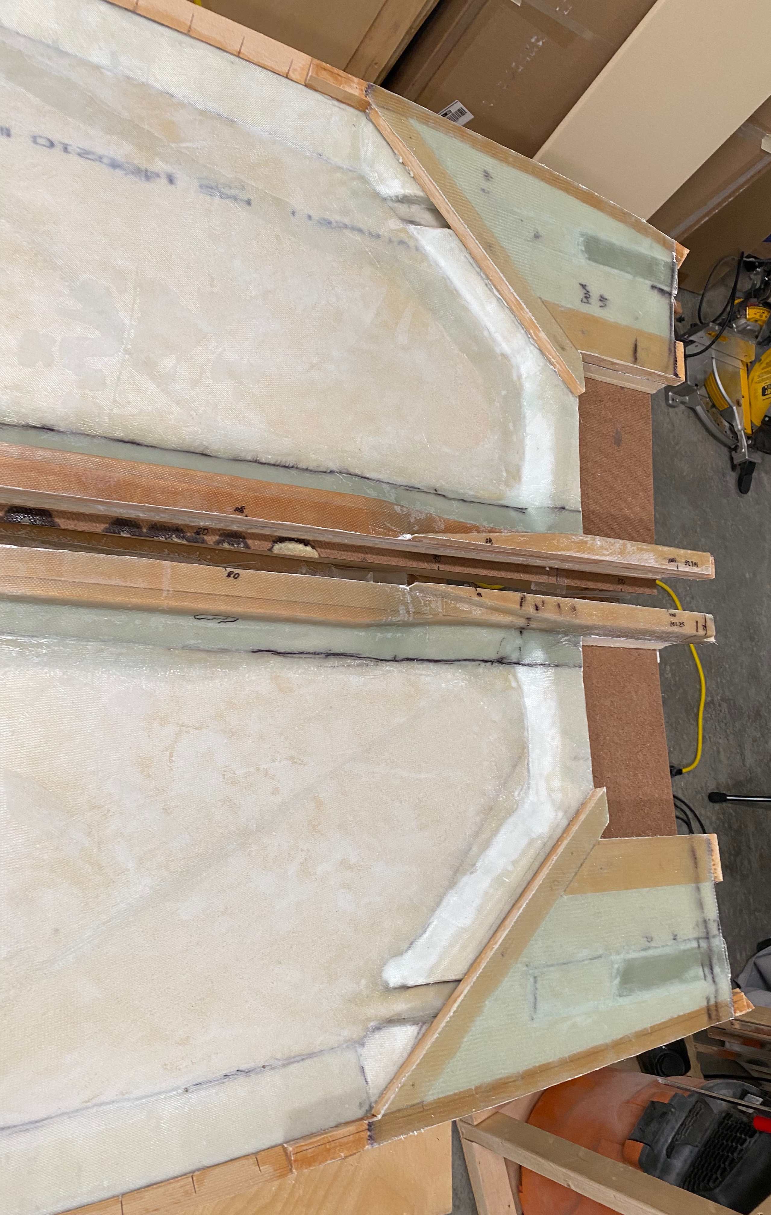
With the lower longerons and LW* stringers installed, the next step is to fill the area between the LW* stringers and the lower longerons with foam, and leaving room for the electrical channel (which will be covered with 1 ply of BID). I made the channel covers using 2 molds made out of 0.75 inch low-density clark foam. I built these molds and channel covers much earlier - before I had done the first glassing of the fuselage sides. These foam pieces serve as a mold. I wrapped them in packing tape and then glassed them with 1 play of BID. Once the stringers were in place, I installed the covers with 5-minute epoxy. Then I cut out foam to fill the area out of the same 0.75 inch low-density clark foam that I had used for the mold. I even re-used parts from the molds to fill in the area above the sloped parts of the covers. I then installed this foam with micro, and filled the voids with dry micro.
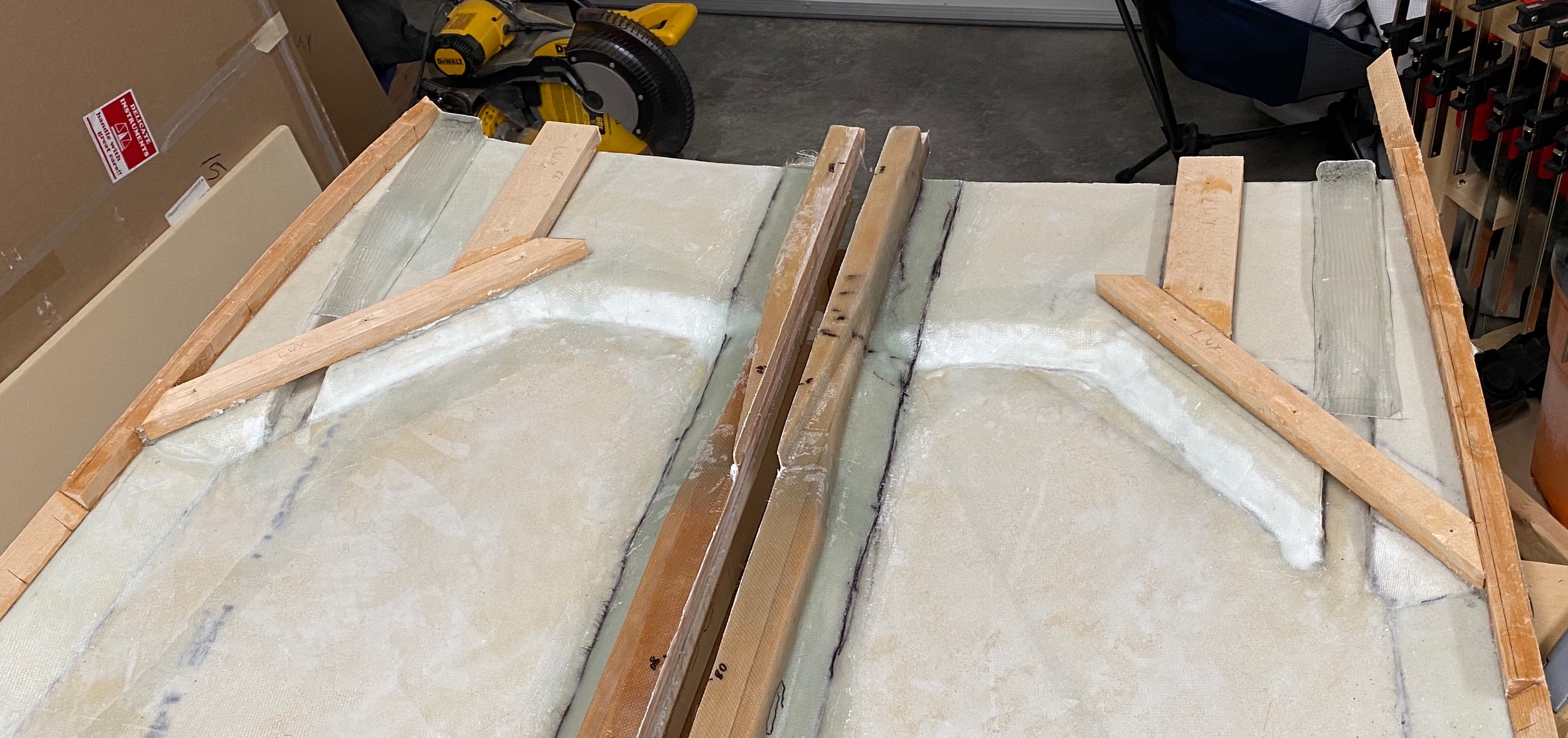
A day later, I came back and glassed that area with 6 plies of BID. Which turned out great.
With the glasswork finished, there are 2 things left for chapter 5: Cut the fuselage sides to length, and cut out the area for the main spar.
When I measured my fuselage sides, I found that they were both too short. One measured 101.5“, the other 101.???“. The plans state these must be exactly 101.75”, and, after panicking a bit, I checked the mailing list. According to discussion in the 1998 archives page, it’s fine that they’re short.
Nat has in person told me twice about builders with the 101.75 a little too short and said it does not matter. Just make sure that everything is square and it will be fine.
If you put the upper longerons where they are supposed to be and nail them as instructed all you have to do is spread the bottom a little. The jigs for the sides on the table aren’t that exact. Nat told me that the long EZ sides were built flat and bent to fit so that also isn’t an exact science. He just has us build them prebent to make assembly easier.
I talked to Nat a long time about this stuff one day and came to the conclusion that I was trying to build to tolerances that are not in the plans and don’t matter. If you have already built these things I guess that it is obvious. It wasn’t obvious to me, I am new to this. That is what we pay Nat the big bucks for though. He was very gracious and helpful despite all my questions that must have seemed silly to him.
After calming down from that, I felt confident continuing. I squared off the forward end of each side, and then cut out the spaces for the main spar. Thus completing chapter 5.
Log
- 2022-06-05, 2022-06-06 - 3D printed FJD jigs & FJA template jig.
- 2022-09-03 - Made FJB, FJC, and FJD jigs. Made most of FJE, but need to trim a little bit more wood to get it to the final shape. Made rough cuts for what will eventually be the FJA jigs.
- 2022-09-04 - A little further progress on one of the FJA jigs.
- 2022-10-15 - Cut one of the FJA jigs to final & correct size. 3 left!
- 2022-10-29 - Ripped a 4x8 sheet of masonite into 2x 21 inch by 8 foot sheets.
- 2022-10-30 - Finished the FJ* jigs.
- 2022-11-04 - Assembled & leveled tables. Installed jigs for eventually creating the upper longerons.
- 2022-11-05 - Epoxied the 105“ spruce strips together and clamped them to the jigs.
- 2022-11-06 - Shaped doublers & stiffeners. Installed them into place. Upper longerons nearly complete!
- 2022-11-08 - Unclamped upper longerons. Removed screws from stiffener. Upper longerons complete! Shaped to both fuselage side forms to the correct shape, finishing them!
- 2022-11-09 through 2022-11-13 - Constructed jig box for fuselage sides, nailed fuselage forms to the jig box, and cut and joined foam for the fuselage sides.
- 2022-11-14 - Started on the fuselage side spacers.
- 2022-11-15 - Cut out the foam that will be the upper and lower side spacers.
- 2022-11-17 - Cut to shape the upper and lower side spacers.
- 2022-11-18 - Installed the upper and lower side spacers.
- 2022-11-19 - Cut and shaped the aft side spacers.
- 2022-11-20 - Installed the aft side spacers, contoured the fuselage sides (added depressions for the control sticks)
- 2022-11-21 - Glassed the electrical channel plugs.
- 2022-11-23 - Glassed the interiors of the fuselage sides, installed the upper longerons.
- 2022-11-24 - Pulled off peel ply from the fuselage sides, inspecting the results.
- 2022-11-25 - Repaired interior layups of the fuselage sides.
- 2022-11-26 - Glassed the upper longerons - which ultimately failed.
- 2022-12-02 - Sanded off glass from failed upper longeron layup.
- 2022-12-03 - Sanded off glass from failed upper longeron layup.
- 2022-12-04 - Redid the upper longeron layup.
- 2022-12-06 - Repaired upper longeron layup (repair part 2). Added initial saw cuts through entire triangular pieces of lower longerons.
- 2022-12-07 - Some additional, final repairs of the interior fuselage side layup that I hadn’t noticed until now. Additionally, measured and marked locations for lower longerons.
- 2022-12-08 - Installed the lower longeron on the port fuselage side.
- 2022-12-09 - Installed the lower longeron on the starboard fuselage side.
- 2022-12-10 - Installed the longeron doublers as well as the LWX and LWY stringers on both fuselage sides.
- 2022-12-11 - Installed electrical cover & filled area between the stringers on the lower longerons with foam.
- 2022-12-12 - Glassed the area between the LWX and LWY stringers on both fuselage sides with 6 plies of BID.
- 2022-12-13 - Trimmed fiberglass from area between LW* stringers and the lower longerons, squared off forward edges, cut out space for main spar.
Last updated: 2022-12-14 12:11:19 -0800