Chapter 7 - Fuselage Exterior
In chapter 7, we take the assembled fuselage built in chapter 6, and do most of the exterior work. This is adding the air intake scoop at the rear, contouring it to have those nice, sleek curves, and glassing everything. At the end of this, the fuselage structure should be at its full strength.
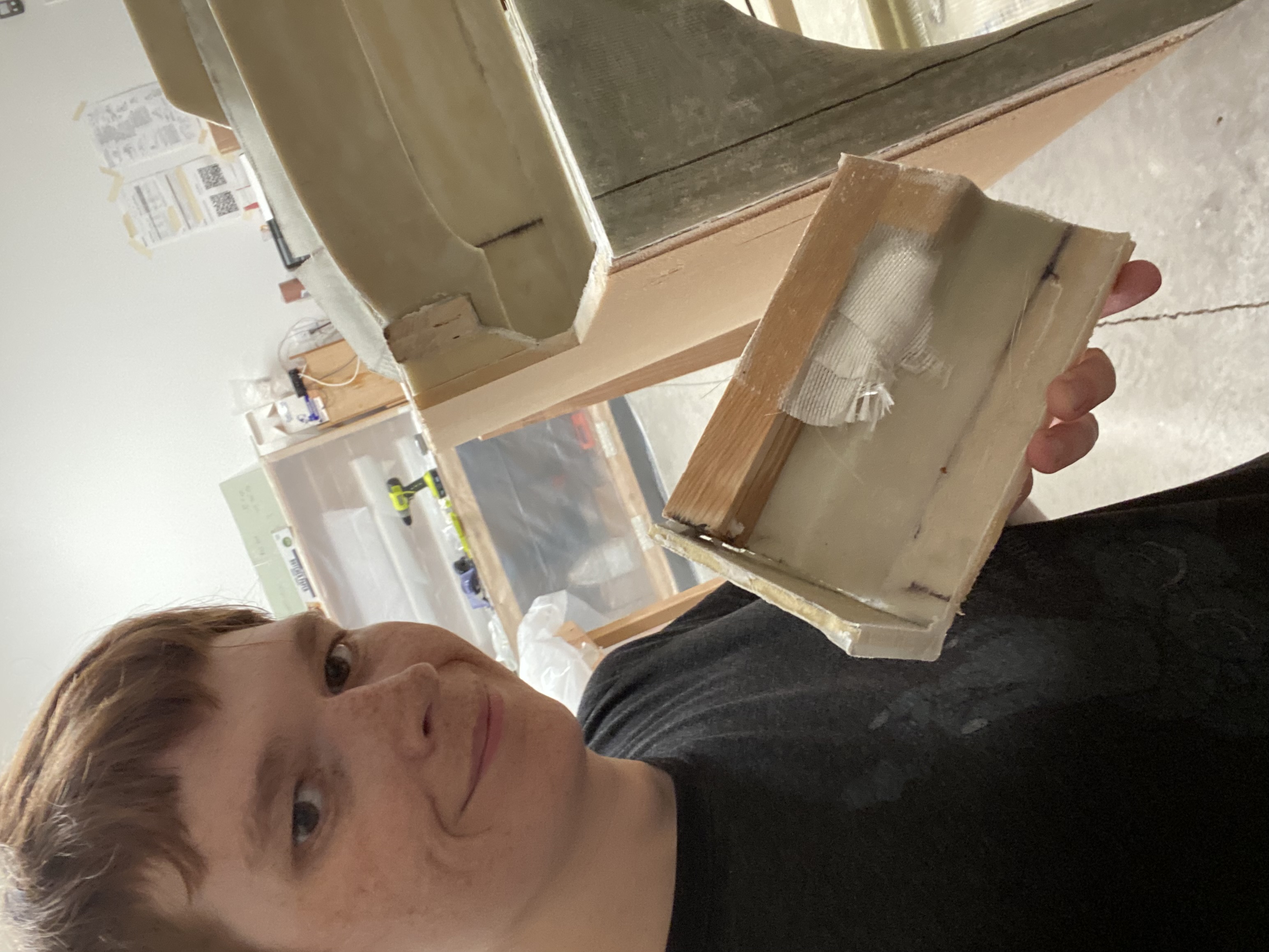
Air Intake Scoop
Contouring Floor
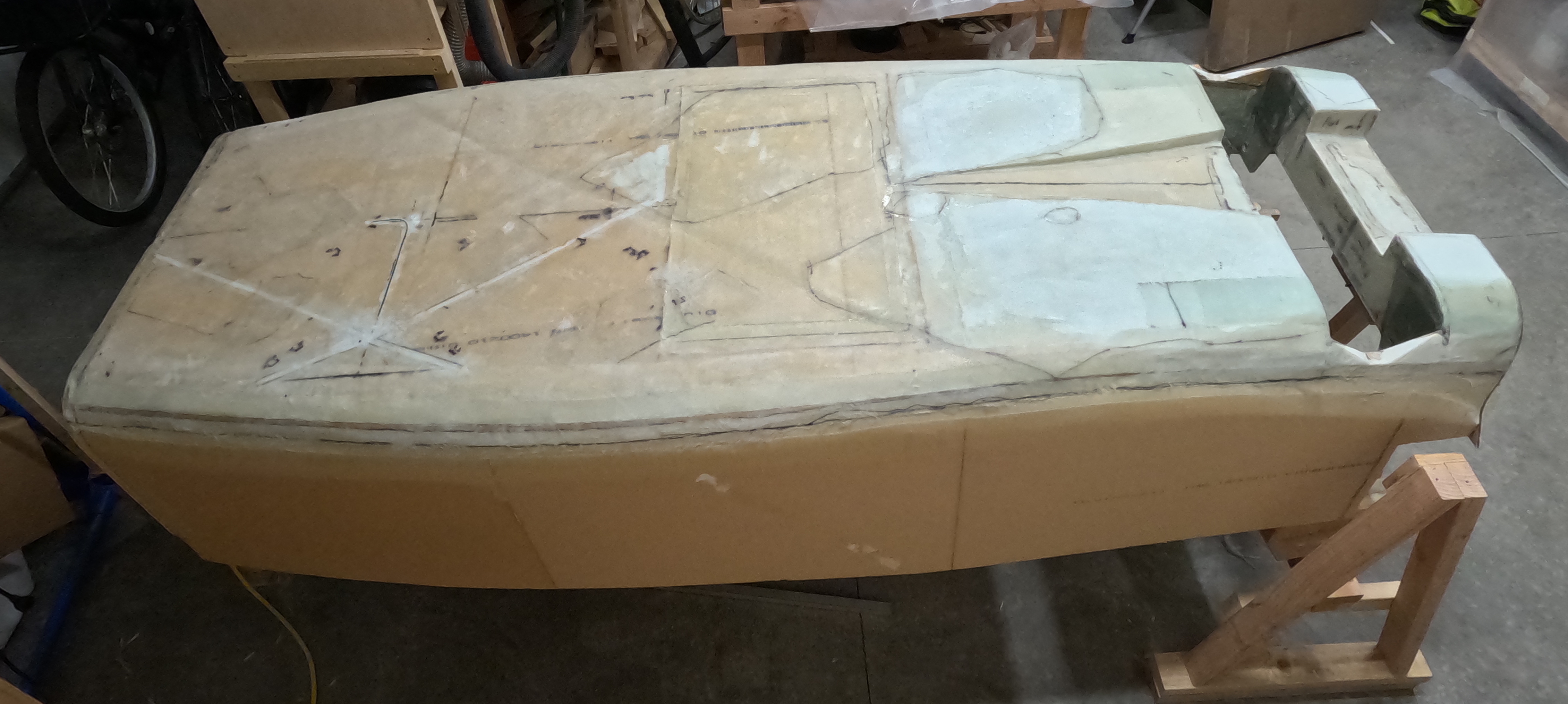
One of the last things to do is to create these 1/16th inch depressions around F22, and around the landing brake. To make these, I set my calipers to 1/16th of an inch, and pressed the depth finder gauge into the foam, creating depressions that were close enough to correct. Then I sanded into the foam until the depressions were gone. These depressions only exist to enable overlap with future parts without creating a bump, so as long as they’re close enough to correct, it’s good enough. Highly recommend this.
Also during this, you have to tape a skirt 1 inch around the landing brake, which will be used later when we pull off the landing brake and and finish making it.
Antennae
Because fiberglass is radio transparent, I can embed the antennae underneath the skin. Giving a slight aerodynamic improvement and a massive aesthetic improvement. With some exception, all of the antennae I’ll be installing are simple dipoles, which can be made out of copper tape. The ones here, definitely so.
I spent some time on the antennae. Initially, I was thinking of placing 3 separate antennae here. A glideslope antenna, a nav antenna, and a marker beacon antenna. After discussing with people, I decided against the marker beacon, and also to combine the nav and glideslope into one. Some people also place a transponder antenna in the floor, which I decided against. I think I’ll place them in the far edge of the strakes, to minimize potential interference with the other antennae.
By the way, when testing antennae layout, I highly recommend using strips of tape to do that. Much cheaper if you decide to move things around.
Once I had the antenna layout figured out, I routed a depression for the copper tape, as well as a path for the coax cable. Then I installed the copper tape, soldered up the antenna, slid some ferrites on, and potted everything.
I did not do any actual testing to check the SWR of this antenna, so the length is based off theoretical numbers - speed of light in a vacuum, with no interference. Which means this is almost certainly too long. However, even if I had used an antenna tester, the test wouldn’t be valid until I finish installing the batteries and other sources of interference.
Glassing Floor
With the antenna installed, I hade no more excuses. Time to glass the floor. The floor is intended to be 2 layers of UNI fiberglass, 60 degrees rotated from each other. One layer rotated 30 degrees one way from the centerline, the other rotated 30 degrees the other way from centerline.
I unfortunately had to glass the floor in multiple parts. After applying the first layer of glass, we ran out of epoxy hardener. We only had enough hardener to glass about a third of the second layer of glass. We peel plied everything and ordered more epoxy.
After inspecting this layup, I noticed a number of errors, and I spent quite some time sanding off fiberglass to repair this. Then I finished the glasswork… let’s say more carefully. I glassed the section between the aft landing gear attach bulkhead and the firewall. Including 3 reinforcement layers over the landing gear attach point and the motor mounts. Then my wife and I did some repair work on the forward third of the fuselage. Then, my wife and I basically redid the middle half or so of the fuselage. Except we still had to do repair work on that, and then I had to repair the repairs. Then I was finished.
fuselage sides.
With the floor glassed, the next step is to contour the fuselage sides.
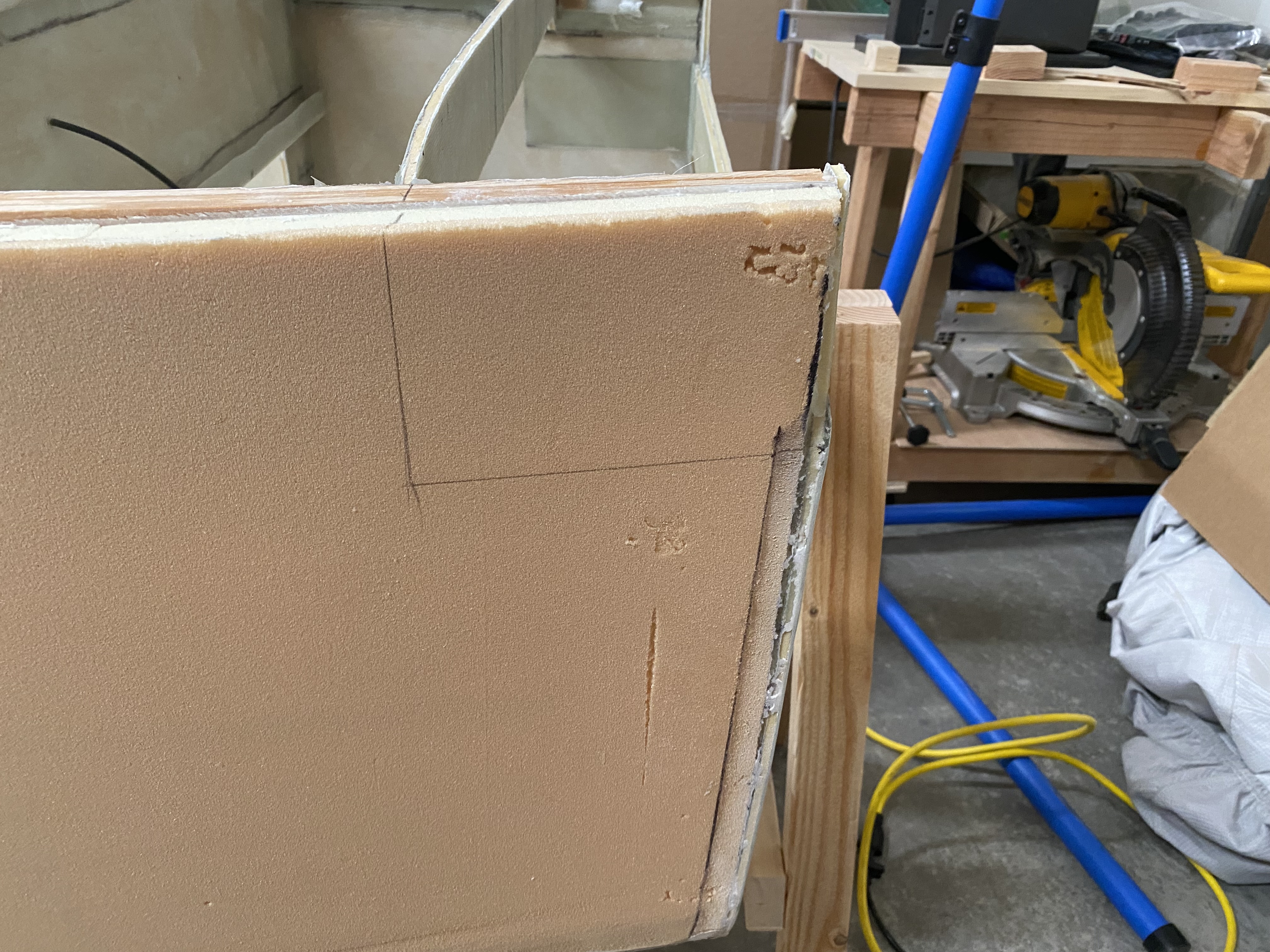
Canard Cutout
Part one of contouring the fuselage sides is making the canard cut-out. The cut-out line vertically is at W.L. 18.9, with the top of the longerons at W.L. 23.0, that means flush with the forward face of F-28, we’re supposed to cut out 2 4.1“ by 6.25“ squares from the longerons, foam, and the top “ears” of F-22. One on either side. I drew lines for this on the foam with pencil, then used the oscillating multitool to cut them out.
Making the fuselage contour templates
Next up is making the templates for the contours. These are 4 templates that represent what the fuselage sides should look like at F-28, F.S. 33, F.S. 38, and at the firewall, with the actual contour of the fuselage smoothly transitioning between them. I printed the 4, glued sandpaper to them as sanding sticks. For the sections where I’m supposed to smoothly transition to the next, I just eye-balled it. It turned out pretty good.
Anyway, I created out the A, B, C, D templates in CAD and created the gcode for them. The next day, I actually printed them. This is because the job would take 9 hours and I’m not at all comfortable running my 3d printer overnight. I’ve never had an issue in the 6 years I’ve owned that printer, but it just feels wrong.
Contouring the Fuselage Sides
With these printed, and the sandpaper attached, I spent a few hours sanding down the upper fuselage sides/upper longerons to the correct contour. Most of the work was done with a belt sander, but I frequently paused to check with the appropriate contour checker. Once it was close enough, I used the contour checker to finalize that sanding.
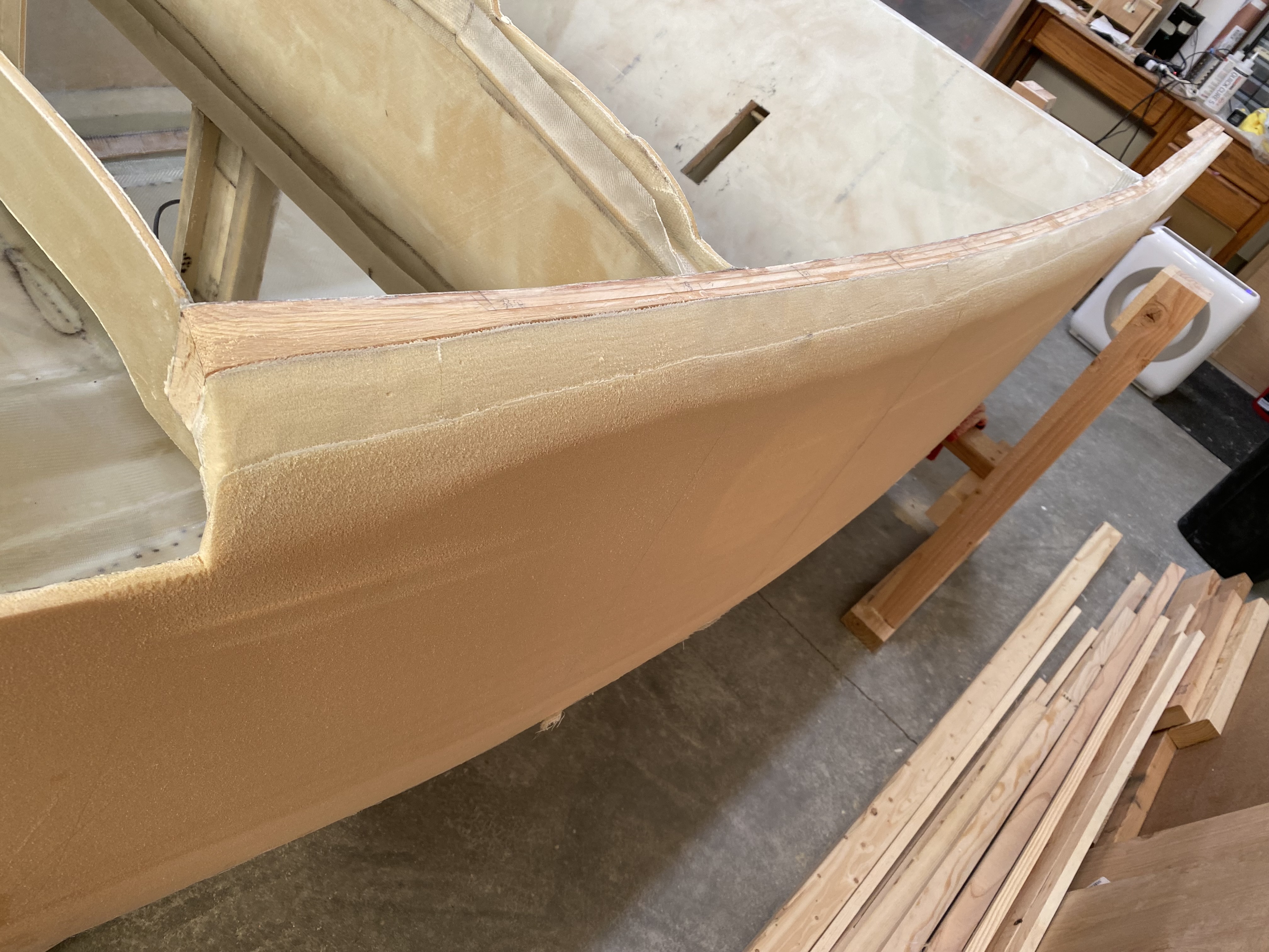
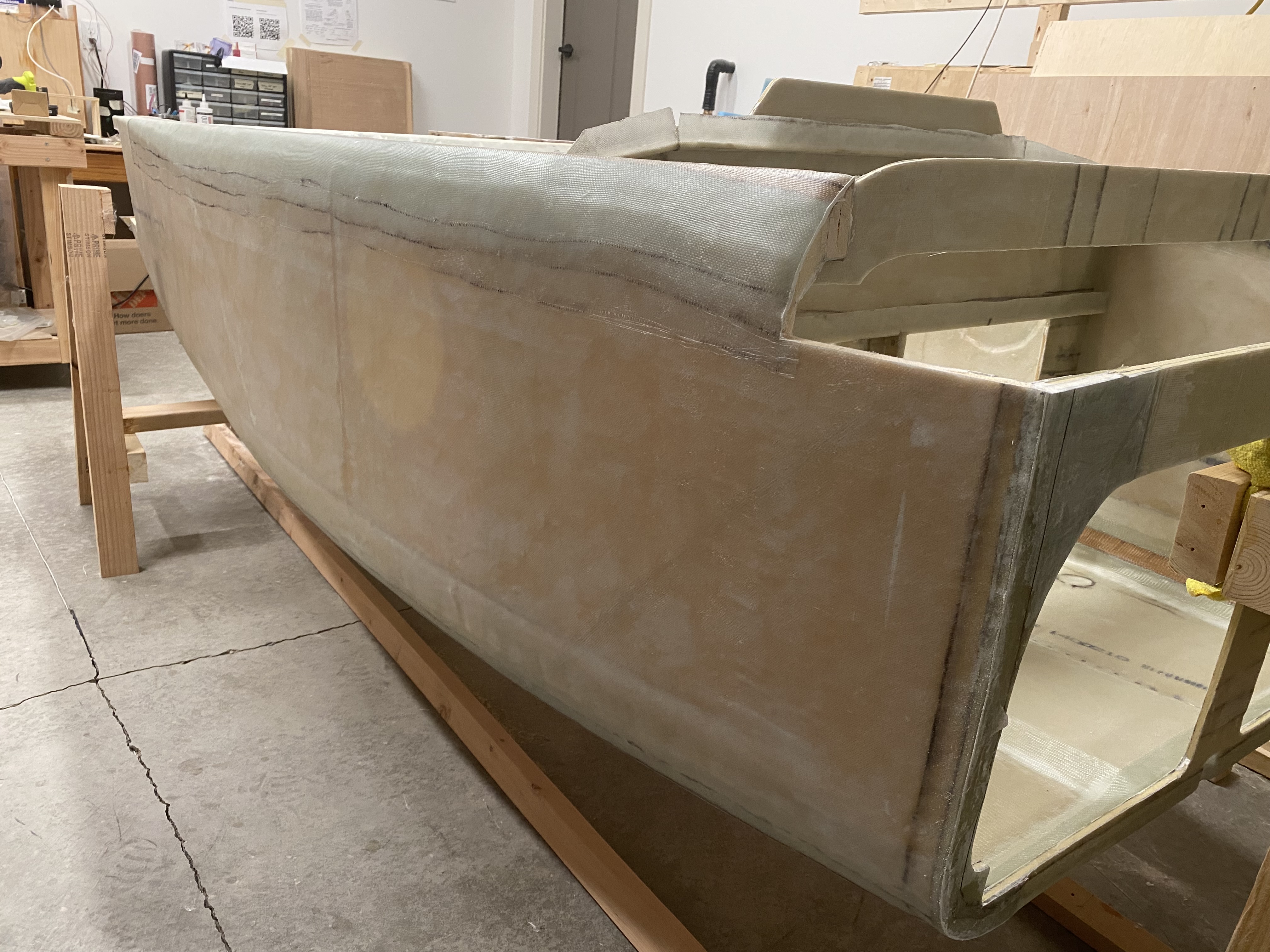
Glassing the Port Side
Once the fuselage sides were contoured, I rotated the fuselage so that the port side was facing up, and I glassed that. It took me about 6 hours to do so, and thankfully I managed to get it all in one shot.
Glassing the Starboard Side
While the port side was still curing, I prepped the fiberglass for the starboard side. I rotated the fuselage so that the starboard side was facing up, and glassed it. It took slightly less time to glass than the port side, but still close to 6 hours. This layup also came out great, thankfully.
Finishing
While the starboard side cured, I trimmed the glass for the port side. Once the starboard side cured, I trimmed the glass on the starboard side. Once both sides were trimmed, chapter 7 was finished!
Log
- 2023-04-06: Made paper template for air intake scoop.
- 2023-04-08: Traced air intake scoop template onto fuselage structure
- 2023-04-09: Installed 1“ and 2“ blocks of urethane foam to form basis for air intake scoop forward of the forward landing gear attach bulkhead.
- 2023-04-10: Built birch reinforcement triangles for landing gear box. Started on birch reinforcement blocks for landing gear box -> firewall.
- 2023-04-11: Attempted install of birch reinforcement blocks, but installed support blocks in incorrect locations… somehow? Would have resulted in a skewed install of reinforcement block. Spent ~2 hours removing hot glue after pulling off support blocks.
- 2023-04-14: Finished removing hot glue from aft landing gear bulkhead and lower firewall. Re-shaped support blocks such that the D parts would be level.
- 2023-04-15: Added layer of fiberglass to repair the sanded-through layers on the aft landing gear bulkhead and the lower firewall. Unfortunately, this glass was not properly wet out, and I discovered that it didn’t adhere correctly and needed to be removed.
- 2023-04-16: Removed incorrectly applied fiberglass on aft landing gear bulkhead and lower firewall. Replaced with fiberglass that was pre-wetted out prior to applying to the correct surface.
- 2023-04-19(?): Installed support parts A, B, C, and D. Glassed the D parts (horizontal supports) with 2-ply BID, overlapping onto the bulkheads 1-inch. Installed urethane foam on all support parts.
- 2023-04-20: Noticed that the port-side vertical support (Part C) between aft landing gear bulkhead and lower firewall was pushed in and was not flush with the lower longerons. Removed support & urethane foam. Remade support (which I determined was quicker than sanding the support down to the wood) and re-attached it. Also re-attached new urethane foam on top of the support. Verified that everything was in the correct spot before closing up.
- 2023-04-21: Measured, cut, and fit foam panels to fill out the air intake scoop from the aft landing gear bulkhead and lower firewall.
- 2023-04-22: Installed foam panels for air intake scoop between aft landing gear bulkhead and lower firewall. Installed additional urethane foam to fill space between start of air intake scoop (as calculated) and what was previously installed.
- 2023-04-23: Built sanding block for sanding naca scoop (glued a sanding belt to a 3ft long 2x4). Applied packing tape to area forward of air intake scoop to prevent accidentally sanding through that foam. No actual sanding, though.
- 2023-04-25: Sanded urethane foam from naca scoop down to the correct shape.
- 2023-04-29: Glassed inner part of naca scoop.
- 2023-05-01: Started repair of naca scoop layup.
- 2023-05-05: Finished repair of the naca scoop layup.
- 2023-05-08: Made scans of the large M-size drawings, 3d-printed contour template for sanding the forward half of the fuselage floor to contour.
- May and June 2023: Sanding fuselage floor to contour.
- 2023-06-18, 2023-06-19: Sanded 1/16th inch depression around landing brake. Placed landing gear in place (supergluing between masking tape).
- 2023-06-21: Built up 1-inch wide “skirt” around landing brake of tape. Sanded 1/16th inch depression in forward half of fuselage floor.
- 2023-06-22: Sanded 1/16th inch depression in forward half of fuselage sides.
- 2023-06-27: Started work figuring out antennae layout. First pass: Marker beacon, 1 nav, and 1 glideslope.
- 2023-06-28: Committed to removing the marker beacon. Will also combine the nav and glideslope into a single antenna.
- 2023-07-08: Routed slots for combined nav1 and glideslope antenna. Routed slots for coax for that antenna. Cut length of coax for nav/glideslope antenna.
- 2023-07-09: Cut copper tape for nav1 and glideslope antenna. Soldered copper tapes to coax to make nav/glideslope antenna. Installed and potted antenna/glideslope antenna.
- 2023-07-10 through 2023-07-22: Prepped fuselage floor for glassing. Sanding, sanding and more sanding.
- 2023-07-17: Glassed approximately 2/3rds of fuselage floor before we ran out of epoxy hardener. Covered floor in peel ply and ordered more epoxy.
- 2023-07-20 through 2023-08-05: Sanded and prepped fiberglass to finish glassing fuselage floor.
- 2023-08-05: Glassed the aft section of the fuselage floor (between the aft landing gear attach bulkhead and the firewall).
- 2023-08-06 through 2023-08-13: Sanded and prepped fiberglass to finish glassing fuselage floor.
- 2023-08-13: Finished glassing fuselage floor.
- 2023-08-15: Repairwork for the fuselage floor.
- 2023-08-16: Finished repairing the fuselage floor.
- 2023-08-22: Released video about process of glassing the fuselage floor exterior.
- 2023-08-22: Rotate fuselage right-side up. Created canard cut-out.
- 2023-08-23: Created 3d models and gcode of the upper longeron contour checkers.
- 2023-08-24: Printed upper longeron contour checkers.
- 2023-08-25: Glued 36-grit sandpaper to upper longeron contour checkers.
- 2023-08-26: Contoured the upper longerons/fuselage sides.
- 2023-08-27 through 2023-08-29: Prepped for glassing the port side.
- 2023-08-30: Glassed the port side.
- 2023-08-31: Prep for glassing the starboard side.
- 2023-09-02: Glassed starboard side.
- 2023-09-03: Trimmed glass from port side.
- 2023-11-20: Came back later and sanded smooth the seams where the fuselage sides transition to the fuselage floor.
Last updated: 2023-11-27 19:14:49 -0800